Simulating an RLC circuit with MultiSim
Note: you can also refer to the MultiSim Tutorial and MultiSim User's Guide on the left side of the E11 web page.
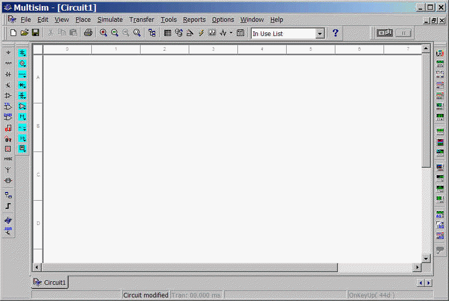
Go to the Windows Start Menu and start the program "MultiSim7". You should get a window like the one shown below:

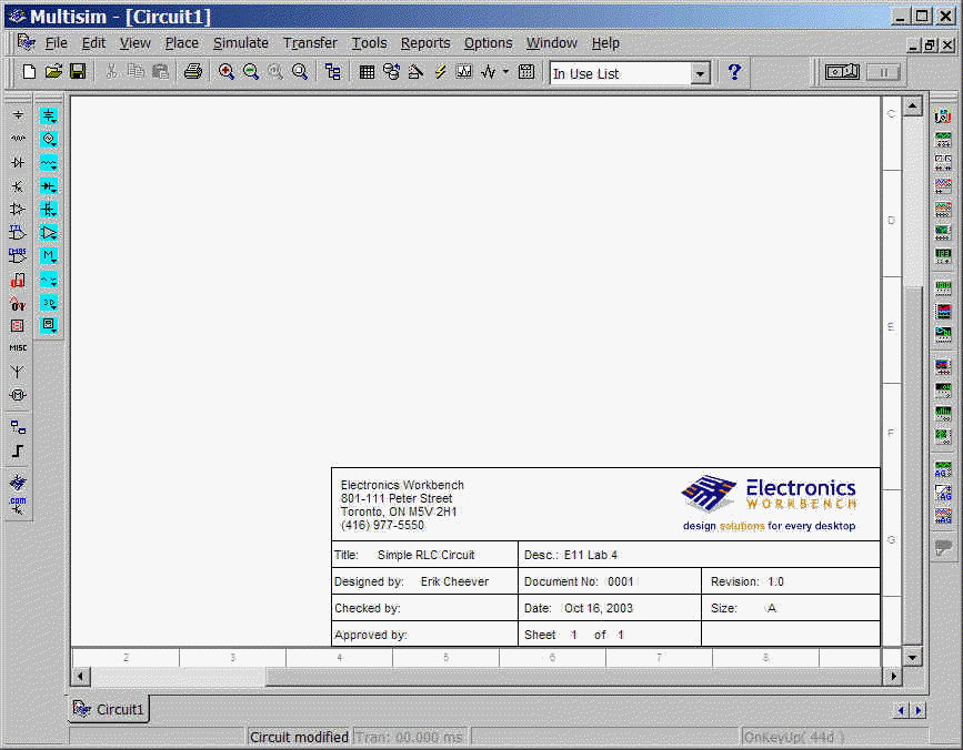
Always add a title block so you can identify your circuit. Go to Place->Title Block and choose the default title block (default.tb7) from the location: C:\Program Files\Multisim7\Titleblocks.
Put your own information into the title block by right clicking on the title block and choosing "Modify Title Block Data...". When that is changed, right click on the title block again and choose "Move to bottom-right". Your diagram should now look similar to the one shown:
Now make sure that all the necessary toolbars are visible. Go to View->Toolbars and make sure "Virtual Toolbar" and "Instrument Toolbar" are selected. The virtual toolbar is the vertical one with cyan buttons on the left, the instrument toolbar is a vertical toolbar along the right side. Their placement on your screen may be different.
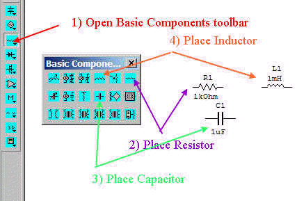
Click to open the Basic Component Bar (the third button down on the virtual toolbar) and place a resistor, capacitor, and inductor. A virtual component is distinct from a physical component in that we don't know the physical size of the part. For simulation we don't need to know the size, if we were making a printed circuit board, we would need to know it.
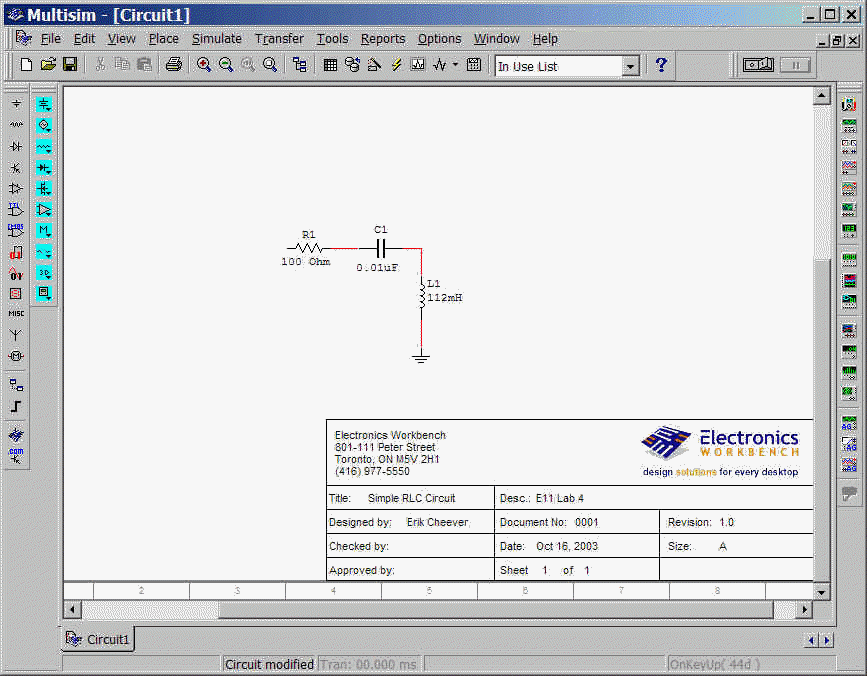
Now double click on each component and change its value. Change R=100W, C=0.01mF, L=112mH. Arrange the components as shown below by clicking and dragging each one. You can rotate a component by selecting it and right clicking on it (or hit ctrl-R on the keyboard). Get the ground symbol from the Power Source Components Bar (the top button on the virtual toolbar). You can place wires by selecting the end of one component and dragging the wire to another component.
Now all we need to do is add a function generator and oscilloscope. Those are found on the Insruments Toolbar.
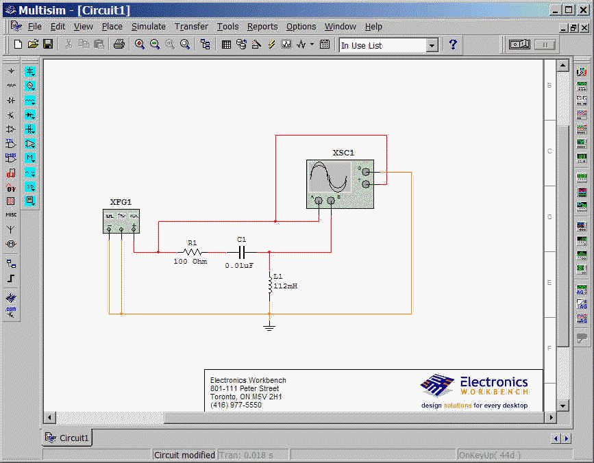
Note that I flipped the function generator horizontally (by right clicking on it) to make wiring neater.
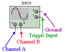
Double click on the function generator and set it to a 100 Hz, 1 volt square wave with a 50% duty cycle (it is high half of the time). Double click on the oscilloscope and set the two channels (A and B) to 1 volt per division. Set the timebase to 1 ms per diviion. The oscilloscope connections are described below. Note that the scope has a distinct trigger input; if you want to trigger from channel A, you must put drag a wire from channel A to the trigger input.
Leave the oscilloscope expanded and hit the on/off (1/0) button on the top right of the screen.
After a screenfull or two, stop the oscillcope.
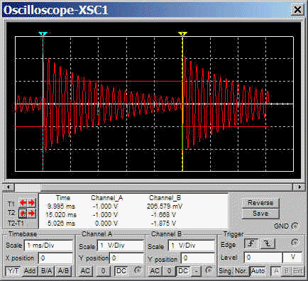
You can use the two cursors on the top of the screen (light blue and yellow) to measure times and voltages on the two traces.
This is the same circuit as in the Background for Lab 4, and for the Procedures. You may have to change component values. You can do that by double clicking on the component.
You have enough information to get you started. If you want to get more elaborate, refer to the MultiSim Tutorial and MultiSim User's Guide.