Welcome to the second lab in E5, where you will learn your way around the Machine Shop in the basement of Papazian (next to Hicks). You will be using the shop to fabricate subsystems for the musical instrument class project, but first you must learn the basics of how to use the machines correctly and safely. Our machinist is Grant Smith, who goes by the name of Smitty. Please pay attention to his overview of the machine shop during lab period this week and next.
For the musical instrument project, I have put you in the following lab groups based on the interview information you obtained in lab last week:
| Lab A | Lab B | Lab C |
Group A1: Pickup and whammy bar
|
Group B1: Master program
|
Group C1: Right-hand mechanism
|
Group A2: Left-hand mechanism
|
Group B2: Left-hand interface
|
Group C2: Right-hand interface
|
Group A3: Left-arm positioning
|
The electric guitar will be played by computer using servos and solenoids. Servos are motors that rotate through a total angle of approximately 180° to a specified angular position (-90° to +90°), as determined by the temporal length (duration) of a square-pulse voltage between 0 and 5 volts. For instance, a pulse of 1.52 ms (milliseconds) duration, repeated every 14 to 20 ms, will cause the arm of the servo to remain at the 0° position; one of 0.6 ms will cause rotation to the maximum counterclockwise position (-90° as seen from above); one of 2.4 ms will cause rotation to the maxium clockwise position (90°). It is up to your group to design a linkage that will translate this motion into something useful as regards your subsystem. Next week, Prof. Orthlieb will spend much of Tuesday's lecture discussing possible mechanical linkages you might employ.
One issue regarding servos is the torque, or axial force, that a servo can produce. The greater the torque, the heavier (and more expensive) the servo. Response time to a change in pulse duration is a second factor, related to the first insofar as greater torque usually means slower response time, and may have bearing on the speed with which the instrument can play different notes. For "Mary had a Little Lamb" a delay may not be a problem; for "Flight of the Bumblebee" it may be a limiting factor. The Futaba FP-S148 is a standard servo whose characteristics you may find on-line. Probably you can start with this one and build a prototype, and request that I buy a different servo only if you find the FP-S148 does not meet your group's needs.
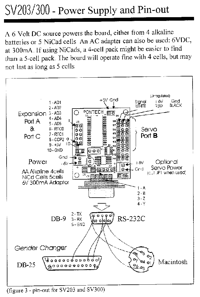
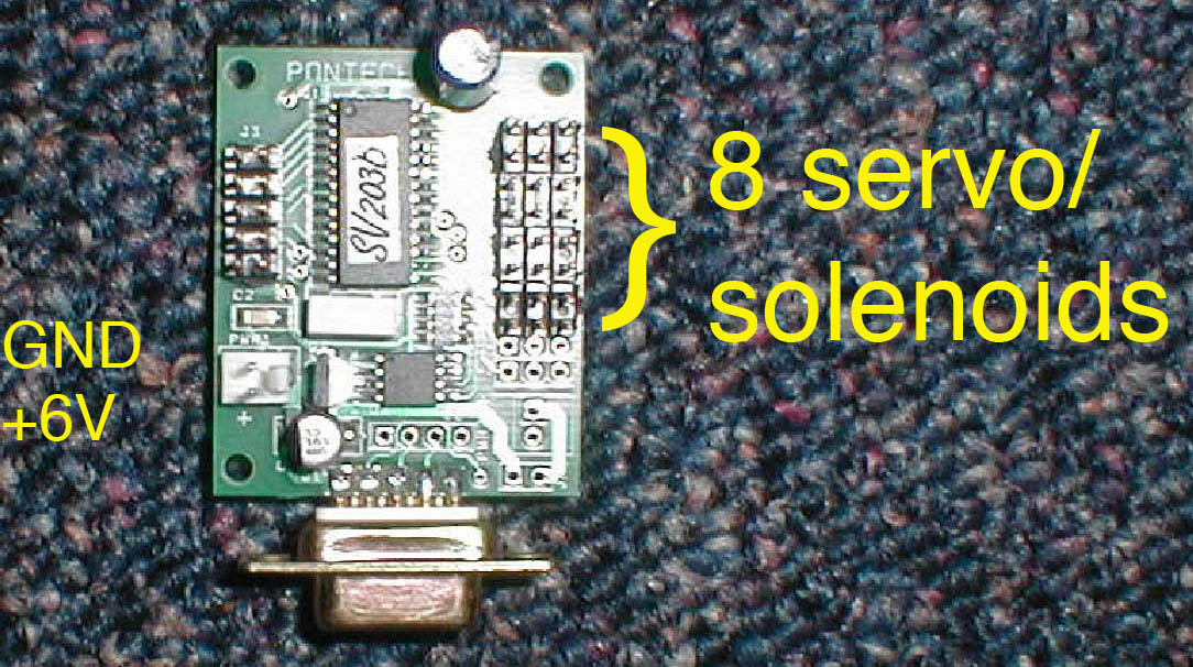
To control the servo, it is typical to use a controller. The controller all lab groups will use is the Pontech SV203B, described in more detail below. The controller is responsible for outputting to up to 8 servos at a time the correct pulse duration sequence to place each servo at an angle specifed by the user. The communication between computer and controller is accomplished via text commands sent from the computer's serial port (using the RS-232 protocol that need not concern us here).
Below is a table outlining all the text commands to which the Pontech SV203B responds:
| Commands | Parameter (n) |
Description |
|---|---|---|
| BDn | 0 to 255 | Board Select (in case of multiple controller boards) |
| SVn | 1 to 8 | Servo Select |
| Mn | 0 to 255 | Move to an absolute location (0 = full CCW, 255 = full CW) |
| In | -128 to 127 | Move relative to current position (negative CCW, pos CW) |
| Dn | 1 to 65535 | Delay in ms |
PSn PCn PTn |
1 to 8 | Raise to high (+5V) a single bit of servo port Force to low (0 V) a single bit of servo port Toggle bit to opposite of what it is currently |
| ADn | 1 to 5 | Get A/D value from A/D channel n. The board will return an integer between 0-255 followed by ASCII 13 corresponding to an analog voltage 0-5V. |
| SOn | 0 to 255 | Shift a byte out to the SPI port |
| SI | None | Shift a byte in from the SPI port |
| WRm n | m = 0-255 n = 0-255 |
Write to internal RAM m is the memory location n is the value to write (integer) |
| RRm | m = 0 to 255 | Read the contents of internal RAM m is the memory location |
| WEm n | m = 0 to 8190 n = 0 to 255 |
Write to external EEPROM m is the memory location n is the value to write |
| REm | m = 0 to 8190 | Read the contents of external EEPROM m is the memory location to read |
As you can see, not only can you change the servo positions, but also detect voltages from each of 5 inputs (A/Ds), read and write to internal memory of the controller, and turns serial (digital) input into parallel, and vice versa (via the SPI port). Moreover, the SV203B has extra memory for holding a BASIC program (you can write) that will execute upon sending the controller the command "SVBAS /RUN". More about this later.
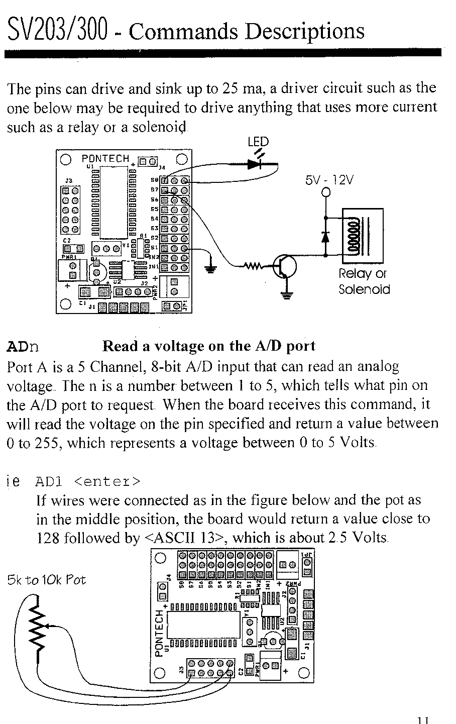
As you may be aware, solenoids are coils of wire in a housing that, when energized, produce a magnetic field that drives an armature forward. The ones we will be using are described in the links below:
The circuit to connect the SV203B controller to the solenoid is shown below (also shown is the simple circuit for a light-emitting-diode (LED) and how to connect the analog inputs, should you have any in your design.
You and your group can begin thinking about what SV203B commands you would use to get the servos and solenoids to move a linkage that you will be designing next week.
|
Comments
or Questions? |
|
 |