The circuit that you will be constructing holds six sensors
that will interface to the robot that you will be building throughout the
semester. Their are four light sensors, and two touch sensors. All
of the sensors feed into a connector that will later be tied into your robot.
Optical Sensor
 The optical sensors are made from Cadmium Sulfide, or
CdS. The cell consists of a thin line of CdS that goes between two
terminals. As light hits the Cadmium Sulfide electrons are dislodged
within the material and become free to carry current, thereby lowering the
material's resistance. The CdS cell is put into a circuit in series
with a 5 volt source and a resistor as shown. The circuit may
look a little funny because there is not a complete loop, but this is
OK. The drawing uses a convention that has a 5 volt source implicitly
in the circuit between the nod labeled "+5V" and the node labeled
"Ground."
The optical sensors are made from Cadmium Sulfide, or
CdS. The cell consists of a thin line of CdS that goes between two
terminals. As light hits the Cadmium Sulfide electrons are dislodged
within the material and become free to carry current, thereby lowering the
material's resistance. The CdS cell is put into a circuit in series
with a 5 volt source and a resistor as shown. The circuit may
look a little funny because there is not a complete loop, but this is
OK. The drawing uses a convention that has a 5 volt source implicitly
in the circuit between the nod labeled "+5V" and the node labeled
"Ground."
The current (I) through the circuit is voltage (V=5 volts)
divided by the total resistance, Rtotal=Rresistor+RCdS.
The voltage across the CdS cell is this current times the
resistance of the CdS cell.

So as light hits the CdS cell, its resistance decreases, as
does the voltage across the cell. By monitoring this voltage we can
measure the light hitting the sensor.
This circuit is repeated 4 times on the circuit you will be
constructing, once for each photo-sensor.
Touch Sensor
 The touch sensor is a little easier to understand. Its
schematic is shown, and consists of a switch and a resistor. Normally
the switch is closed, so the output voltage is zero volts (Ground).
When the switch opens up, current ceases to flow, so the voltage across the
resistor goes to zero. Since the voltage on both sides of the resistor
is the same, the output voltage becomes 5 volts.
The touch sensor is a little easier to understand. Its
schematic is shown, and consists of a switch and a resistor. Normally
the switch is closed, so the output voltage is zero volts (Ground).
When the switch opens up, current ceases to flow, so the voltage across the
resistor goes to zero. Since the voltage on both sides of the resistor
is the same, the output voltage becomes 5 volts.
There are two of these circuits on your robot, to detect
collisions with objects on either side.
Completed Schematic
A completed schematic is shown below. There are four
light sensor circuits, and two touch sensors (a different circuit symbol is
used for the touch switches, but it is functionally equivalent to the one
shown above). All of the signals, including +5 volts and ground, then
go to a connector (labeled DIP14HEADER) which
will feed the signals to the computer on your robot. This diagram
doesn't show resistors connected to the switches because these are actually
on the board that holds the computer.
Your going to be constructing this circuit using a printed
circuit board, or PCB. The PCB is a thin insulating board onto which a
circuit is printed. You then connect your components to the circuit with
solder. Solder is a combination of metals, usually 60% lead/40% tin,
that is melted with a soldering iron to connect electrical
components. The solder melts at about 190°C (370°F).
It has a core of flux which is seen boiling away as the solder is
applied -- the flux is a chemical that improves the quality of the connection
being made. If you haven't soldered before, please read my
page that describes soldering (and perhaps check out some of the links at
the bottom of that page). Solder contains lead, so try to avoid
breathing the fumes, and wash your hands when you are done. If you are
experienced in soldering, let somebody else in the group (with less
experience) do the soldering while you try to help them learn the proper
technique.
 The
diagram shows the layout of the printed circuit board. The green line
represent traces (copper lines that are printed on the board, then covered
with solder to prevent oxidation) on the top side of the board -- called the
component side. The red lines represent traces on the bottom side --
called the solder side. On this layout you can see where the switches
(S1 and S2), the CdS cells, the resistors and the 14 pin connector are placed.
The
diagram shows the layout of the printed circuit board. The green line
represent traces (copper lines that are printed on the board, then covered
with solder to prevent oxidation) on the top side of the board -- called the
component side. The red lines represent traces on the bottom side --
called the solder side. On this layout you can see where the switches
(S1 and S2), the CdS cells, the resistors and the 14 pin connector are placed.
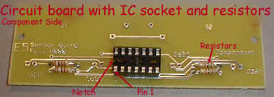 To start the
construction place the 14 pin socket and four 1000 ohm resistors on the board
with the component side (with most of the writing) facing up, as shown.
Solder all the components, and cut the leads of the resistors close to the
board. There should be a completed board to which you can compare yours
board.
To start the
construction place the 14 pin socket and four 1000 ohm resistors on the board
with the component side (with most of the writing) facing up, as shown.
Solder all the components, and cut the leads of the resistors close to the
board. There should be a completed board to which you can compare yours
board.
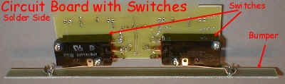 Next,
screw two switches to the solder side of the board with four 3/4" #4-40
screws. The 3/4" corresponds to the length of the screw, #4 refers
to the diameter, and 40 refers to the size of the thread (40 per inch).
Next feed a wire up through one of the holes under one of the three terminals
on on one of the switches, and hook it onto the terminal. Solder
both ends of this wire. Repeat with the other terminals until all six
terminals are soldered. Attach the bumper as shown by placing wires
through the holes, and twisting the wires around the leaves of the switches
(thin bus wire works well). Don't attach too firmly; the switches should
have a little play, but the should be in no danger of falling off.
Next,
screw two switches to the solder side of the board with four 3/4" #4-40
screws. The 3/4" corresponds to the length of the screw, #4 refers
to the diameter, and 40 refers to the size of the thread (40 per inch).
Next feed a wire up through one of the holes under one of the three terminals
on on one of the switches, and hook it onto the terminal. Solder
both ends of this wire. Repeat with the other terminals until all six
terminals are soldered. Attach the bumper as shown by placing wires
through the holes, and twisting the wires around the leaves of the switches
(thin bus wire works well). Don't attach too firmly; the switches should
have a little play, but the should be in no danger of falling off.
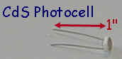 The last step is
to attach the photocells. Take several photo-cells and measure their
resistance, which should decrease as more light falls upon them. Go
through them, one at a time, until you find four that have similar resistance
when point in the same direction (so that the same amount of light falls on
each). You won't be able to get a really close match, but shoot for the
same value within about 20-30% -- the match isn't critical, or even totally
necessary. Slip a 7/8" length of shrink wrap tubing on on
leg. Carefully insert the leads of the photocell from
the component side, until the shrink wrap butts up against the PCB. Hold
the photocell there,
and solder. Hold the photocell by the top part, the leads will get very
hot as you solder them (metal conducts heat very well). Repeat until all
4 are attached. When finished, cut the excess leads off from the back of
the PCB.
The last step is
to attach the photocells. Take several photo-cells and measure their
resistance, which should decrease as more light falls upon them. Go
through them, one at a time, until you find four that have similar resistance
when point in the same direction (so that the same amount of light falls on
each). You won't be able to get a really close match, but shoot for the
same value within about 20-30% -- the match isn't critical, or even totally
necessary. Slip a 7/8" length of shrink wrap tubing on on
leg. Carefully insert the leads of the photocell from
the component side, until the shrink wrap butts up against the PCB. Hold
the photocell there,
and solder. Hold the photocell by the top part, the leads will get very
hot as you solder them (metal conducts heat very well). Repeat until all
4 are attached. When finished, cut the excess leads off from the back of
the PCB.
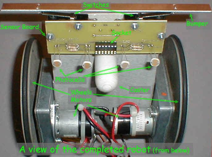
 Attach
the bumper loosely to the two switches using buss wire. The completed board (attached to the robot) is shown . A
larger photo of the whole robot (as seen from
below), is also available.
Attach
the bumper loosely to the two switches using buss wire. The completed board (attached to the robot) is shown . A
larger photo of the whole robot (as seen from
below), is also available.
